How to Install Milan Solid Brass Bronze Commercial Sensor Faucet & Automatic Soap Dispenser
Installation Steps For Fontana Milan Solid Brass Bronze Finish Wall Mount Dual Automatic Commercial Sensor Faucet And Automatic Soap Dispenser
- Before you begin, please read the installation instructions below. Observe all local building and safety codes.
- Unpack and inspect the product for any shipping damages. If you find damages, do not install.
- Please note all showers must be installed by a professional and certified plumber otherwise warranty might be voided.
|
faucet
|

|

|
Sensor Faucet Installation Instructions
|
Step 1:
|
sensor
|
Step 2:
|

|
|

|
|
|
|
|
|
Parts:
|
|
|

|
|
|
|
|
|
|
|
Step 3:
|
|
Step 4:
|

|
|

|
|
|
|
|
|
Step 5:
|
|
Step 6: (Drywall Anchor Method)
|

|
|

|
|
|
|
|
|
Step 7:
|
|
Step 8: (Threaded Shaft Method)
|

|
|

|
|
|
|
|
|
Step 9:
|
|
Step 10: (Elbow Method)
|

|
|

|
|
|
|
|
|
Step 11:
|
|
Step 12: (Plywood Method)
|

|
|

|
|
|
|
|
|
Step 13:
|
|
Step 14:
|

|
|

|
|
|
|
|
Control Box Installation
|
Step 1:
|
|
Step 2:
|

|
control
box
|

|
|
|
|
|
|
Step 3:
|
|
|

|
|
|
|
|
|
|
|
|
|
1. Carefully screw aerator into spout using the included tool.
2. Mark center-point of faucet spout and drill a 3/4” hole on the previously marked center-point.
Note: It is recommended to horizontally align faucet spout with the center of the sink drain and vertically 7-10” above the sink drain. To comply with ADA standards, faucet spout must be mounted less than 50" from the finished floor.
3. There are four methods of securing the spout to the wall:
a. Drywall Anchor Method: Mark the slots of the spout’s flange and drill 3 equally-spaced 3/16” (4mm) holes. Insert the drywall anchors into the holes. Feed the hose and sensor cable through the hole in the wall, starting with the sensor cable first. Then, attach the spout to the wall using the supplied screws.
b. Threaded Shaft Method: Thread on the threaded rod onto the faucet spout. Feed the hose and sensor cable through the hole in the wall, starting with the sensor cable first. Then, attach the flanged nut onto the threaded shaft of the spout by hand, behind the wall. Ensure the spout is correctly oriented into the basin and continue tightening the nut with a wrench. Note: Avoid over-tightening to prevent damage to the wall.
c. Elbow Method: Mark the slots of the spout’s flange and drill 3 equally-spaced holes with a minimum drill bit size of 3/16" (4mm). Slip the sensor cabling and flexible hose through the elbow such that the brass on the elbow contacts the backside of the wall. Thread the M4 screws through the spout flange and into the threaded holes of the elbow. Tip: By hand, insert each screw into the threaded holes, and barely tighten. Then use a screwdriver to tighten each screw in a clockwise pattern little by little until tightened.
d. Plywood Method: If the restroom has a plywood backing of minimum 1/2” thickness behind the wall, use a hand drill to fasten the spout to the wall using the provided 3 coarse-threaded screws. Pre-drilling pilot holes are not required.
4. Slide escutcheon over the spout and onto the wall surface.
Control Box Installation
1. Remove the four screws from the control box. Remove the control box cover. Remove the battery box from the control box, and gently remove the screw from the battery box cover. Install AA batteries in the orientation shown. Note: Use only alkaline AA batteries. Re-install the battery box cover, matching the alignment arrows together. Set the battery box back into the control box, and re-install the control box cover using the previously removed screws.
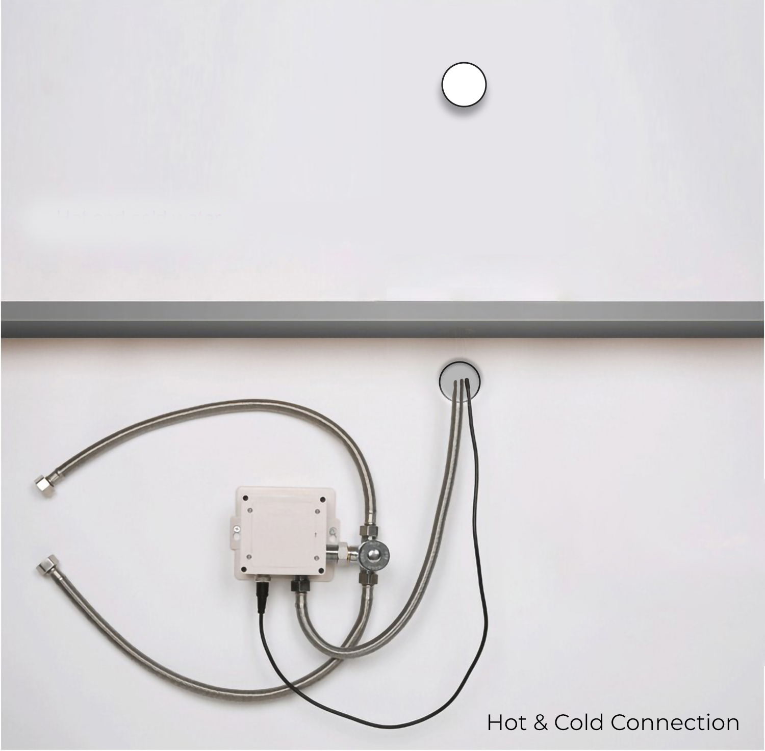
2. Choose a location under the sink basin to mount the control box, such that the sensor cable, flexible hose, and incoming water supply all connect to the control box. Under the sink basin, drill a hole minimum 3/4” to fit the sensor cable and flexible hose from the spout. Feed the sensor cable and flexible hose through the hole.
3. Mount the control box to the wall in the orientation shown. Drill four 1/8" (3mm) holes as shown, and push drywall anchors into each hole. Secure the control box to the wall with the drywall screws.
4. Connect the incoming water supply line to the control box, at the connection marked Inlet.
5. Thread on the swivel nut to the hose by hand. Tighten with a wrench.
6. Connect the faucet hose to the control box, at the connection marked Outlet.
7. Slide sensor cable connector over the sensor cable connector on the control box and tighten by hand.
Note: Prior to connecting the sensor cable to the control box, open the water supply stop valve and ensure the sink basin is completely clean and clear of objects, or the sensor will not correctly calibrate. See page 6 for instructions on recalibration. Please wait approximately 60 seconds after connecting the sensor cable for sensor calibration to complete and to begin using the faucet.
|
|

|
|
|
Automatic Soap Dispenser Installation Instructions
|
Step 1:
|
sensor
|
Step 2:
|

|
|

|
|
|
|
|
|
Step 3:
|
|
Step 4:
|

|
|

|
|
|
|
|
|
Step 5:
|
|
Step 6:
|

|
|

|
|
|
|
|
|
Step 7:
|
|
Step 8:
|

|
|

|
|
|
|
|
|
Step 9:
|
|
Step 10:
|

|
|

|
|
|
|
|
|
Step 11:
|
|
Step 12:
|

|
|

|
|
|
|
|
|
Step 13:
|
|
Step 14:
|

|
|

|
|
|
|
|
|
|
|
|
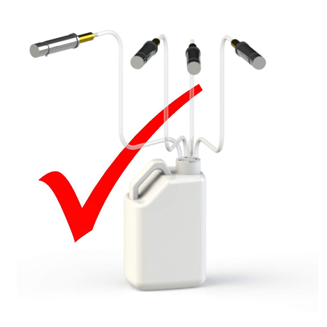
Correct Way
|
|
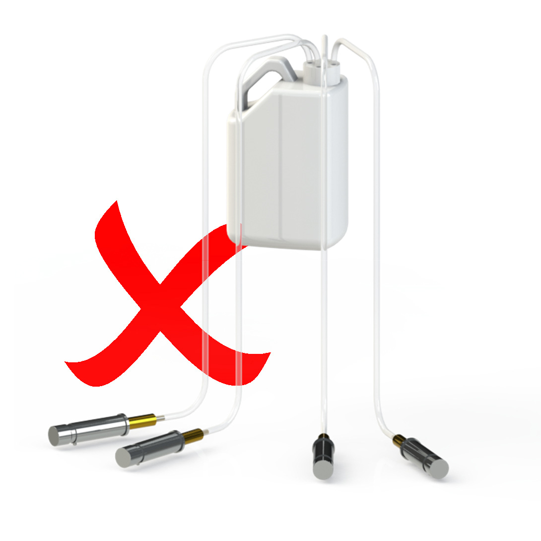
Incorrect Way
|

|
|

|
|
|
|
|
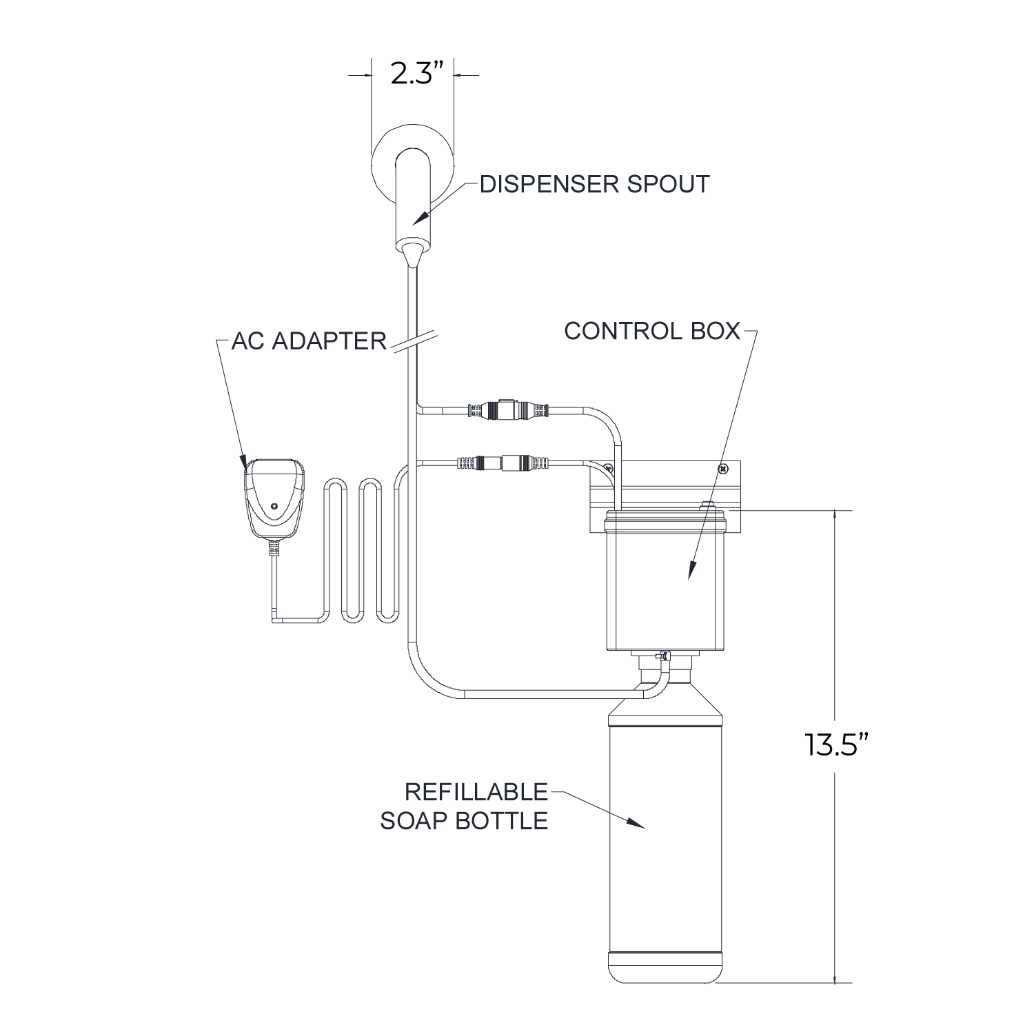
1. The dispenser is mounted directly to the wall above the basin. The control box is mounted below the basin and the soap tube and sensor connector are run through the wall behind the basin and back out the front of the wall to the control box below the basin.
2. Remove the escutcheon from the dispenser assembly by unscrewing counter-clockwise. Correctly orient the dispenser and mark the holes.
3. Remove the two retention screws and remover the body from the base. Drill 3/16" holes on the marks and insert anchors. Attach the base to the wall using the supplied screws
4. Feed the soap tube and sensor connector through the wall and reattach the body to the base by tightening the retention screws.
5. Reinstall the escutcheon by threading it clockwise onto the base.
Note: It is recommended to horizontally offset the soap dispenser spout with the faucet 4 - 6” and to install vertically 6-10" above the sink drain at the same height as the faucet. To comply with ADA standards, the center-point of the soap dispenser spout must be less than 50" from the finished floor.
Control Box Installation
1. Place the mounting bracket on the wall as a guide and mark the hole locations. Drill 3/16" holes on the marks, insert the anchors and attach the mounting bracket to the wall with the screws.
2. Align the tab on the back of the control box with the mounting bracket hole and hang the control box.
3. Connect the sensor connector and power connector from the dispenser and A/C adapter to the control box.
4. Push the soap tube onto the outlet connection on the control box. Secure the tube with the clamp.
Soap fill and Startup
1. Remove the soap bottle from the control box by unscrewing the soap bottle counter-clockwise. Fill the soap bottle with soap of the appropriate viscosity. Do not overfill the soap bottle.
2. Re-attach the soap bottle to the control box, making sure that the soap input tube is inside the soap bottle. Depress the green system prime button until soap comes from the nozzle. The system is now ready to use.
|
|

|
|
|
|
|
|
|
|
|
CARE AND MAINTENANCE
If the soap dispenser fails to function correctly, firstly check all connections are tight and free from air leaks. If dispenser still fails to function, place manifold into a bottle of warm water. Pump the warm water through the dispenser to dislodge any dried soap residue and then refit manifold into soap bottle.
Water marks and soap residue on polished chrome surfaces are best cleaned using warm water and a mild detergent. Use a stainless steel cleaner for brushed stainless steel soap dispensers. Never use an abrasive cloth to remove stubborn stains. Dry with a soft clean cloth.
• ALWAYS mount the soap tank feeding the dispenser/s BELOW the level of the dispensers
• NEVER mount the soap tank feeding the dispenser/s ABOVE the level of the dispensers
Also please note:
The soap type and brand used in these dispensers should not be altered throughout the life of the dispenser as mixing soaps can affect their chemical characteristics and cause them to become more aggressive. If another soap type or brand is needing to be used then the previous type must be thoroughly flushed through and cleaned from the soap dispensers and system prior to its use.
|
|
How to Install Fontana Milan Solid Brass Bronze Finish Wall Mount Dual Automatic Commercial Sensor Faucet And Automatic Soap Dispenser
|
|
|
Our Milan Oil Rubbed Bronze finish wall mount dual-sensor faucet and soap dispenser is an eye-catching design which is both functional and nice to look at, the sensor faucet as well as soap dispenser has been developed with ease in mind. This dual sensor faucet and soap dispenser is an elegant fixture that will seamlessly fit in any contemporary restroom. Its easy use technology definitely make your cleaning job easier. This cast brass electronic motion faucet is now available in dual function water and soap dispenser sensor faucet. This touch less motion sensor faucet reduces the transfer of germs by preventing cross-contamination and re-contamination of germs and bacteria by not touching the faucets or handles. Fits all standard US plumbing. Uses 4 AA Alkaline Batteries (purchase separately).Water Pressure: 0.5 - 7.0 KGS /cm, 10-125 psi. With its micro-computer controlling its action, the motion sensor faucet can self adjust its best detection zone as per the color and shape of lavatory. Sensor faucet with built-in Infrared AI smart-chip no water dripping design 100% touch-free operation.
|

|
|
|
|
Fontana Milan Solid Brass Bronze Finish Wall Mount Dual Automatic Commercial Sensor Faucet And Automatic Soap Dispenser Features:
|
|
|
Brand Name: FontanaShowers
Model Number: FST9900
Complete motion detection touchless operation
Sensitive Sensor with Infrared AI Smart-Chip Automatic Soap Dispenser
Factory set to 30-second Auto Shutoff (can be adjusted).
Water Pressure: 0.5 - 7.0 KGS /cm , 10 - 125 psi
Solid Brass Construction, Bronze Finish
Easy to Install - Instructions Included
Water-resistant solenoid enclosure
Advanced energy-saving design for long-lasting battery life
Sensor faucet comes complete with Hoses & Accessories
Power Supply: AC 110 V and DC 6 V (batteries not included)
AC/DC power option
ADA Compliant
Easily can be installed in new or retrofit applications
|
|
|
|